Digital Devices || Analog Devices || Motors || Shields || Ping
Motors
Section 5.3

Servo Motors
Servo motors are smart devices with an integrated circuit on board. They use PWM pins and the length of the pulse to set the motor position; it holds it there until you tell it otherwise.
Sending the correct pulses to the motor is quite complicated so we use a 'library' to do this for us.
These servos can be set anywhere between 0 - 180 degrees and cannot rotate like a normal motor. You need to map the values sent so they do not go outside of this 0-180 range.
They have internal gears slowing them down and giving them a higher torque (turning force).

Servo Motor Example Code


Stepper Motors
Stepper motors have multiple internal coils which can be activated in a sequence to turn the motor with incredible precision.
The one on the left has a step resolution of 7.5 which means one step turns the motor 7.5 degrees. There are therefore 48 steps per 360 degree rotation.
Unlike the servos these motors have the ability to rotate through 360 degrees and beyond, we can also count how many steps we have taken and know the exact angular position of the shaft.
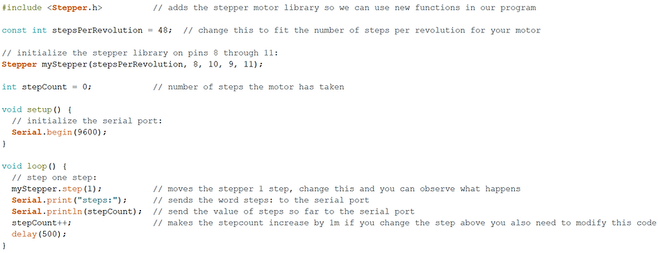
Read the commented code below and see how it has been implemented.
You can see the setpsPerRevolution has been setup for these specific motors, if you use a different model others you will need to look at the datasheet and modify the code

Stepper Motor Example Code


DC Motors and Motor Controller
As you may a;ready know when DC motors are connected to a battery it makes them rotate. You may also know that you can make the motor rotate in the other direction by swapping the positive and the negative wires around.
A DC motor controller does all of the wire switching for you and more.
-
It controls the direction of the flow of current through the coils, and therefore the rotation direction.
-
It supports PWM so you can specify the power and therefore the speed of the motor.


The logic table above shows the HIGH and LOW values of the pins relating to the desired effect. This L298N motor driver has 2 channels so it could be used to control two motors at the same time.
-
Here you will learn how to control one motor, but its the same process for two just with extra wires and some duplicated code.
-
You can connect any 2 digital pins on the Arduino to 'L1' and 'L2' (I & J on the diagram)
-
You can also connect a PWM supporting digital pin to 'Enable' (H on the diagram) if you also want speed control, if no speed control is needed just leave the small jumper pin on there.
Motor Controller Example Code


External power for motors
-
When you use motors for low power application it is ok to use the Arduino to supply the power.
-
If you want to use bigger motors, or multiple motors or notice the Arduino is behaving strangely (power is cutting out, motors behave unexpectedly) you may require an external power source
-
A separate battery is required as otherwise too much current is drawn through the Arduino's microprocessor
-
COMMON GROUND means you must connect the negitave of the power source with the ground of the Arduino. (that is the single black wire on the board)


